Doing better than Lego House

Introduction

In this post I’ll talk about a small experience I had with a Lego set that I acquired on my trip to Legoland in Billund, Denmark (yes, the original Legoland 😃). I’ll not talk about the trip itself, which was the best of my life. It was so because I had the opportunity to bring my daughter and my niece to see their happy faces when they entered in the park. Rather, I’ll talk about a small project that was motivated by a special LEGO set I bought on LEGO House.

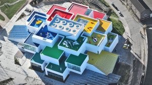
Lego House (https://www.legohouse.com/)

The Lego House is amazing. It is located close to Legoland, also in Billund. I won’t talk about it because I would have to write a book 😄. The point is that, there is a Lego Store inside it, and they sell a very special LEGO set: the set #40179, or “Personalised Mosaic Picture”. It is a set that contains only a large base plate with 48×48 spaces (currently the largest in a set) and about 4500 1×1 plate divided in 5 different colours (yellow, white, black and two shades of grey).

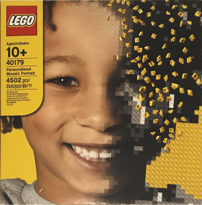
Lego Custom Mosaic set

The goal of the set is to allow the owner to “draw” a mosaic picture with the 1×1 plates on the big base plate. What makes this set special is the instructions. The instructions are a big 1:1 picture the size of the plate itself which indicates the position and colour of all 1×1 little plates. You may ask: What picture comes in the set? yours!

The Lego Set

As I mentioned, it is your picture that comes with the instructions! When you buy the set in the store, they guide you to a small photo booth where they take your picture to make the instructions. The whole process is made for children and it is a piece of work 😆. First, they take some pictures of your face and show to you in a screen inside the booth. There, you see how the mosaic is going to look like when you assemble it. When you are satisfied with the mosaic, you go out of the booth and wait your custom set. The set is delivered automatically via a small hole beside the cabin. While you wait, you watch an animation of a couple of LEGO mini figures dressed as workers and producing your set. When done, the booth spits out your big set with your picture turned into The LEGO instructions poster.

Doing that for my 3 year old

I could not leave The LEGO House whiteout buying one of those. Of course I would not put my picture on it. Instead, I wanted to make one for my little daughter. And that was when the problem arose. The lady in the store told me that it would be very very difficult to get a good picture for a 3 year old. First, she is not tall enough. Then, she would not be quiet enough and her little head would not be close enough to the camera to make a good mosaic. All that is true. Remember that the picture should be perfect because the mosaic would be a representation of her face using only 4 shades of grey (and possibly a yellow background) in a 48×48 pixel matrix.

But wait… What if I did the mosaic myself? This set is practically only “software”. Regardless of the picture, the set have 4500 1×1 plates and a giant 48×48 base and that’s it! The rest is image processing! I talked to the lady in the store and told her that I would take the risk of not having a good picture. She told me about all the difficulty, bla bla bla, but I insisted: “Trust me, I’m an engineer” (Just kidding, I told her I just want the 4500 1×1 plates 😅). She finally agreed. We even tried to get a “reasonable” mosaic, but it is really very very difficult. The lady was very nice and was very patient. We tried like 6 or 8 times but the best we could do was this:

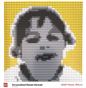
Original Lego mosaic picture

I didn’t like the mosaic at all (too flat shapes) but remember that I had other plans 😇. Besides, my little one does not like pictures and it is rare to get a picture with her smiling on it. Anyways, with the set bought, I was ready to do my small weekend project with it as soon as I was back.

Doing a better mosaic

The first thing I had to do was to find a better picture to be turned into the mosaic. So I started to dig for a picture that I like (at least one with her smiling. 😅). It didn’t even needed to be a full picture. I could (and still can 😊) take a picture and use it. The picture would be reduced to 48×48 pixels anyway, so practically any picture where she appear, could be a potential mosaic candidate.

Crop of the picture used to make the first mosaic

With the picture chosen, it was time to do the magic. I’ll won’t detail exactly the steps I did to process the image because this is very dependent on the crop that you do and things like illumination, tones, etc. Depending on the picture, it would require a very specific and different set of steps. The result of the photoshop processing was the following

Result of the “mosaicfication” of the picture. Left: Greyscale picture 48×48. Right: Mosaic picture 48×48 with only 4 levels of grey (and a background)

Python code

Now that had the image is very small (48×48 pixels) with only 5 different “colours”. That is what makes this step not trivial. When the processing done, in theory I could print it on a large paper and start building the set. But I figure that I could easily mistake a shade of grey with another or get lost in the middle of the assembly. So, I decided to ask for computer help. I did a small python program that loads the image and aid me in the assembly process.

The script do two main things: First, it translates the “colours” of the image into something more readable like letters (A to E according to the shade of grey in the pixel). Then, it creates an “assembly” sequence that will help me to stick the small plates in the right place on the big base plate. This second step is what makes the assembly more “comfortable”. The idea was to show the image in the screen and highlight each line one at a time. In the highlight, instead of show the letter in the place where I should put each plate, it would show each “block” of the same colour, showing the amount of plates needed and the corresponding letter for each block. Then, it was a matter of put all this in a loop for each line and wait for a keypress at each step to continue the assembly.

Gif of the steps showed by the program. In each highlighted line, the blocks of pieces with the same colour have the indication of the letter and the amount of plates needed

The whole python code is very very simple.
#!/usr/bin/env python3
# -*- coding: utf-8 -*-
"""
Created on Wed Aug  8 18:16:32 2018

@author: allanmartins
"""
from matplotlib import pyplot as plt
import numpy as np

img = np.uint8(255*np.round(255*plt.imread('bebel48x48x5.png')))

values = np.unique(img)

for (i, v) in zip(range(len(values)), values):
    img[img==v] = 5-i


fig = plt.figure(figsize=(20, 20))

line = -0.5
for I in img: 
    plt.cla()

    arrayTmp = np.concatenate((np.array([1.0],dtype=np.float32),np.abs(np.diff(I))))
    
    arrayTmp = np.greater_equal(arrayTmp, 0.5)
    
    idx = [i for (i, v) in zip(range(len(arrayTmp)),list(arrayTmp)) if v>0]
    levels = I[idx]
    idx.append(48)
    
#    fig = plt.figure(figsize=(15, 15))
    plt.set_cmap('gray')
    plt.imshow(img, vmin=1, vmax=6)

    for i in range(len(idx)-1):
        lineColor = [1, 0.2, 0.2]
        textColor = [1, 1, 1] if not levels[i] == 5 else [0, 0, 0]
        plt.plot([idx[i]-0.5, idx[i+1]-0.5, idx[i+1]-0.5, idx[i]-0.5, idx[i]-0.5], [line, line, line+1, line+1, line], color=lineColor, linewidth=4)
        plt.text(-0.75+(idx[i]+idx[i+1])/2.0, line+0.75, '%c : %d'%(levels[i]+64, idx[i+1]-idx[i]), color=textColor, size=15)


    plt.show(block=False)
    fig.canvas.draw()
    fig.canvas.flush_events()


    sQtd = ''
    sLevels = ''
    for d,l in zip(np.diff(idx), levels):
        sQtd += '%4d'%d
        sLevels += '%4c'%(l+64)
        
    print(sQtd + 'n' + sLevels)
    print('n')
    input()
    
    line += 1


The result

As result, I have the infra-structure now to make any mosaic with any picture. I just have to be patient to disasbemble the old one and follow the script to assemble a new one. The final result for the first image is here (and a time lapse of the assembly). I don’t remember exactly the time it took to finish, but by the number of frames in the time lapse I estimate about 2h for the whole process.

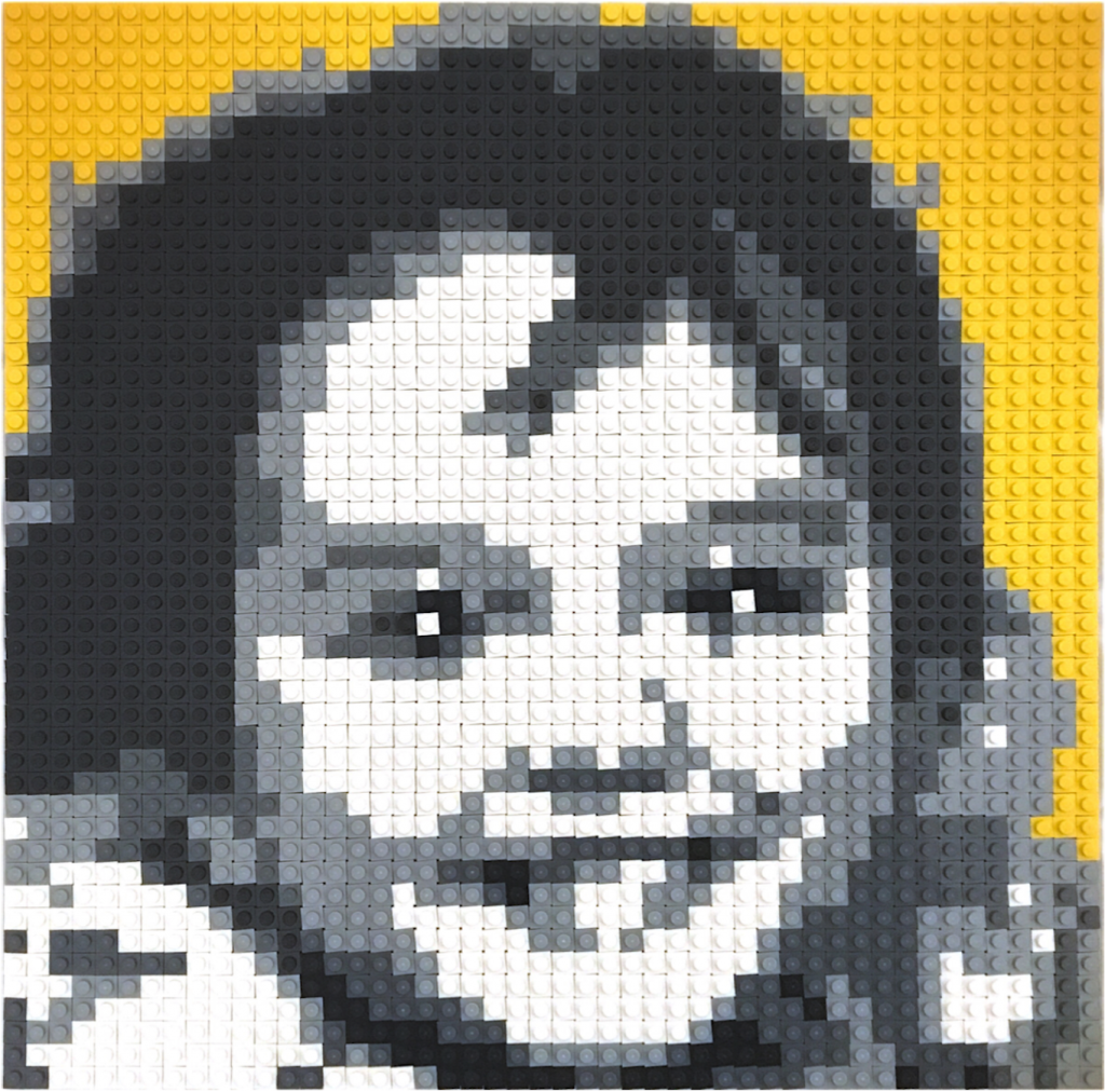
Custom Lego mosaic picture

Time lapse of the assembly process

Conclusion

Despite the title of this post, LEGO is making an awesome work with the set. If you google for images of mosaics you will see that, in general, if you follow the guidelines, your LEGO mosaic will be cool! it is very difficult for a consumer product to be perfect with this kind of technology (image processing, colour quantisation and etc). So, it is good to know some coding in cases like this, which allow us to take advantage of the “hardware” of the set (4500 1×1 plates) and do our own custom “custom LEGO Mosaic set” 😀.

I hope you liked this post! See you in the next one!

2+

We take gears for granted…

Introduction

Since I was a kid, I always loved toys with “moving parts”. In particular, I was always fascinated with the transmission of the movement between two parts of a toy. So, whenever a toy had “gears” in it, for me, it looked “sophisticated”. This fascination never ended and a couple of year ago when I bought my 3D printer, I wanted to build my own “sophisticated” moving parts and decided to print some gears.

I didn’t want to just download gears from thingverse.com and simple print them. I wanted to be able to design my own gears in the size I want with the specifications I needed. Well… I’d never thought a would have so much fun…

So, in this post I will talk briefly about this little weekend project of mine: Understanding a tiny bit about gears!

The beautiful math behind it

At first I thought that the only math that I needed was the following \[ \frac{{{\omega _1}}}{{{\varpi _2}}} = \frac{{{R_2}}}{{{R_1}}} \] In another words, the ratio of the angular speeds is proportional to the ratio of the radius of the gears. Everyone know that, right? If you have a large gear and a small one, you have to rotate the small one a lot to rotate the big one a little. So, to make a gear pair that doubles the speed I just had to make one with, say, 6cm of diameter and the other with 3cm. Ha… but how many teeth? What should be their shape? Little squares? Little triangles? These questions started to pop and I was getting more and more curious.

At first I thought I use a simple shape for the teeth. I would not put too many teeth because they could wear out with use. Also, not too few because they had to be big and I might end up with too much slack. Gee, the thing started to get complicated. So, I decided to research a bit. For my surprise I found out that the subject “gears” is a whole area in the field of Mechanical Engineering. First thing I notice is that most of the gears have a funny rounded shape for the teeth. Also, they had some crops and hollow spaces in the teeth that vary from gear to gear. Clearly those were there for a reason.

Those “structures” are parameters of the gear. Depending on the use, material or environment, they can be chosen at design time to optimise the gear function. However, practically all gears have one thing in common : The contact of the gear teeth must be optimum! It must be such that during rotation, the working gear tooth (the one that is being rotated) must “push” the other gear tooth in such a way that the contact is always perpendicular to the movement as if we had a linear or straight object pushing another in a straight movement. Moreover, the movement must be such that when one tooth leaves the contact region, another tooth must take over, so the movement is continuous (see figure).

Figure 1: Movement being transmitted from one tooth to another. The contact and the force is always perpendicular and is continuously transmitted as the gear rotates. (source: Wikipedia. See references)

This last requirement can mathematically be archived by a curve called “Involute”. Involute is a curve that is made when you take a closed curve (a circle for example) and start to “peel of” it’s perimeter. The “end” of the peeling is the points in the involute (see figure).

Figure 2: Two involute curves (red). Depending on the starting point, we have different curves. (source: Wikipedia. See references)

So, the shape of the teeth of the gears are involutes of the original gear shape. Actually not all gears are like that. The gears that are, are called “Involute Gears”. Moreover, gears do not need to be circular. If you have a gear with another shape, you just need to make its teeth curved as the involute of the shape of the gear.

The question now is: How to find the involute of a certain shape?

Following the “peeling” definition of the involute, it is not super hard to realise that the relationship between the involute and its generating curve is that, at each point in the involute curve, a line perpendicular to it will be tangent to the original curve. With that, we have the following relation: \[ \begin{array}{*{20}{l}} {\dot X(t)\sqrt {{{\dot x}^2}(t) + {{\dot y}^2}(t)} = \dot y(t)\sqrt {{{(x(t) – X(t))}^2} + {{(y(t) – Y(t))}^2}} } \\ {\dot Y(t)\sqrt {{{\dot x}^2}(t) + {{\dot y}^2}(t)} = – \dot x(t)\sqrt {{{(x(t) – X(t))}^2} + {{(y(t) – Y(t))}^2}} } \end{array} \] Which is a weird looking pair of differential equations! There, \((X(t), Y(t))\) is the parametric curve for the involute and \((x(t), y(t))\) is the parametric curve for the original curve.

Some curves do simplify this a lot. For instance, for a circle (that will generate a normal gear) the solution is pretty simple: \[ \begin{array}{l} X(t) = r\left( {\cos (t) + t\sin (t)} \right)\\ Y(t) = r\left( {\sin (t) – t\cos (t)} \right) \end{array} \]

Matlab fun

So, how do we go from the equation of one involute to the drawing of a set of teeth?

To test the concept, first I implemented some Matlab scripts to draw and animate some gears. In my implementation I used a circular normal gear, so the original curve is a circle. Nevertheless, I implemented the differential equation solver using Euler’s method so I could make weird shape gears (in a future project). The general idea is to draw one pieces of involutes starting at each tooth and going to half of the tooth. Then, draw the other half starting from the end of the tooth until the end of it. The “algorithm” to draw a set of involute teeth is the following

  • Define the radius and number of teeth
  • define \(t = \theta\) and \(dt = d\theta\) (equal to some small number that will be the integration step)
  • Repeat for each n from 0 to N-1 teeth:
    • Start with \( \theta = n\frac{2\,\pi}{N}\)
    • update the involute curve (Euler’s method)
      \(X(\theta) = X(\theta) + {\dot X(\theta)}\,d\theta \)
      \(Y(\theta) = Y(\theta) + {\dot Y(\theta)}\,d\theta \)
      until half of the current tooth
    • Update the angle in the clockwise duration \( \theta = \theta + d\theta\)
    • Start with \( \theta = (n+1)\frac{2\,\pi}{N}\)
    • update the involute curve
      \(X(\theta) = X(\theta) + {\dot X(\theta)}\,d\theta \)
      \(Y(\theta) = Y(\theta) + {\dot Y(\theta)}\,d\theta \)
      until half of the current tooth
    • Update the angle in the anti-clockwise duration \( \theta = \theta – d\theta\)
If we just follow the algorithm above, our gear, although functional, won’t appear as a traditional gear. All the auxiliary parameters are not present (like the slack between teeth, cropping, etc). It will basically be a flower like shaped thing (see figure bellow).

Figure 3: Example of a gear with all auxiliary parameters equal to zero

When you use the technical parameters for a gear, it starts to shape familiar. The main parameters are called “addendum”, “deddendum” and “slack”. Each one control some aspect of the mechanical characteristics of the gear like flexibility of the teeth, depth of the teeth, etc. The next figure illustrates those parameters.

Figure 4: Parameters of a gear

The next step was to position a pair of gears next to each other. First, we choose the parameters for the first gear (addendum, radius, number of teeth, etc). For the second one, we choose everything but the number of teeth. That must be computed form the ratio of the radius.

For the positioning, we would put the first gear at the position \((0.0, 0.0)\) and the second one at some position \((x_0,0.0)\). Unfortunately the value of \(x_0\) is not simply \(r_1 + r_2\) (sum of the radius) because the involutes for the teeth must touch at a single point. To solve this, I used a brute force approach. I’m sure that there is a more direct method, but I was eager to draw the pair %-). Basically, I computed the curve for the right gear first tooth and the left gear first tooth (rotated \(2\pi/N\) so they can match when in the right position). Initially I positioned the second one at \(r_1 + r_2\) and displaced bit by bit until they touched only in only one place. In practice I had to deal with a finite number of points for each curve, so I had to set a threshold to consider that the two curves are “touching” each other.

With the gears correctly positioned it was time to make a 3D version of them. That was easy because I had the positions for each point in the gears. So, for each pair of points in each gear I “extruded” a rectangular patch by \(h_0\) in the z direction. Then I made a patch with the gear points and copied another one at \(z = h_0\). Voilà! Two gears that match perfectly!

The obvious next step was to animate them 😃! That is really simple because we just need to rotate the first by a small amount, rotate the second by this amount times the radius ration and keep doing that while drawing the gear over and over. The result is a very satisfying gear pair rotating!

Figure 5: Animations of two gear sets with different parameters.

Blender fun

Now that I got used to the “science”, I was ready to 3D print some gears. For that, I had to transfer the design to Blender, which is the best 3D software in the planet. The problem is that it would be a pain in the neck to design the gear in Matlab, export to something like stl format, test it in Blender and, if it’s not quite what I wanted, repeat the process, etc. So, I decided to make a plugin out of the algorithms. Basically I just implemented all the Matlab stuff in python, following the protocol for a Blender plugin. The result was a plugin that adds a “gear pair” object. The plugin adds a flat gear pair. In general we must extrude the shapes to whatever depth we need in the project. But the good thing is that we can tune the parameters and see the results on the fly (see bellow).

Figure 5: Blender plugin

With the gears in blender, the sky is the limit. So, it was time to 3D print some. I did a lot of tests and printed a lot of gears. My favourite so far is the “do nothing machine” gear set (see video) it is just a bunch of gears with different sizes that rotates together. My little daughter loves to keep rotating them 😂!

Figure 6: Test with small gears

Figure 7: Do nothing machine with gears

Conclusions

As always, the goal of my posts is to share my enthusiasm. Who would have thought that a simple thing like a gear would involve hard to solve differential equations and such beautiful science with it!

Thanks for reading! See you in the next post!

References

[1] – Wikipedia – Involute Gears
[2] – Wikipedia – Involute Curve
[3] – GitHUB – gears
2+

Blender+Kinect

Introduction

In this small project, I finally did what I was dreaming on doing since I started playing with the Kinect API. For those who don’t know what a Kinect is, it is a special “joystick” that Microsoft invented. Instead of holding the joystick, you move in front of it and it captures your “position”. In this project I interfaced this awesome sensor with an awesome software: blender.

Kinect

The Kinect sensor is an awesome device! It has something that is called a “depth camera”. It is basically a camera that produces an image where each pixel value is related to how far is the the actual image that the pixel represent. This is cool because, on this image, its very easy to segment a person or an object. Using the “depth” of the segmented person on the image, it is possible, although not quite easy, to identify the person’s limbs as well as their joints. The algorithm that does that is implemented on the device and consists of a very elaborated statistical manipulation of the segmented data.

Microsoft did a great job in implementing those algorithms and making them available in the Kinect API. Hence, when you install the SDK, you get commands that returns all the x,y,z coordinates of something around 25 joints of the body of the person in front of the sensor. Actually, it can return the joints of several people at the same time! Each joint relates to a link representing some limb of the person. We have, for instance, the left and right elbows, the knees, the torso, etc. The whole of the joints we call a skeleton. Hence, in short, the API returns to you, at each frame that the camera grabs, the body position of the person/people in front of the sensor! And Microsoft made It very easy to use!

With the API at hand, the possibilities are limitless! So, you just need a good environment to “draw” the skeleton of the person and you can do whatever you want with it. I can’t think of a better environment than my favorite 3D software: blender!

Blender side

Blender is THE 3D software for hobbyist like me. The main feature, in my opinion, is the python interface. Basically you can completely command blender using a python script inside the blender itself. You can create custom panel’s, custom commands and even controls (like buttons, sliders and etc). Within the panel, we can have a “timer” where you can put code that will be called in a loop without block the normal blender operations.

So, for this project, we basically have a “crash test dummy doll” made of armature bones. The special thing here is that this dummy joints and limbs are controlled by the kinect sensor! In short, we implemented a timer loop that reads the Kinect positions for each joint and set the corresponding bone coordinates in the dummy doll. The interface looks like this. There is also a “rigged” version where the bones are rigged to a simple “solid body”. 
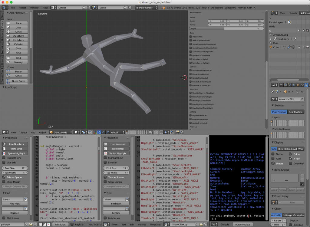
Hence, the blender file is composed basically of tree parts: the 3D body, the panel script and a Kinect interface script. The challenge was to interface the Kinect with python. For that I used two awesome libraries: pygame and pykinect2. I’ll talk about them in the next section. Unfortunately, the libraries did not like the python environment of blender and they were unable to run inside the blender itself. The solution was to implement a client server structure. The idea was to implement a small Inter Process Communication (IPC) system with local sockets. The blender script would be the client (sockets are ok in blender 😇) and a terminal application would run the server.

Python side

For the python side of things we have basically the client and the server I just mentioned. They communicate via socket to implement a simple IPC system. The client is implemented in the blender file and consists of a simple socket client that opens a connection to a server and reads values. The protocol is extremely simple. The values are sent in order. First, all the x’s coordinates of the joints, then y’s and then z’s. So, the client is basically a loop that reads joint coordinates and “plots” them accordingly in the 3D dummy doll.

The server is also astonishingly simple. It has two classes: the KinectBodyServer class and the BodyGameRuntime class. In the first one we have a server of body position that implements the socket server and literally “serves body positions” to the client. It does so by instantiating a Kinect2 object and, using the PyKinect2 API, asks for joint positions to the device. The second class is the pygame object that takes care of showing the screen with the camera image (the RGB camera) and handling window events like Ctrl+C, close, etc. It also instantiates the body server class to keep pooling for joint positions and to send them to the client.

Everything works synchronously. When the client connects to the server, it expects to keep receiving joint positions until the server closes and disconnects. The effect is amazing (see video bellow). Now, you can move in front the sensor and see the blender dummy doll imitate your moves 😀!

Motion Capture

Not long ago, big companies spent a lot of money and resources to “motion capture” a person’s body position. It involved dressing the actor with a suit full of small color markers and filming it from several angles. A technician would then manually correct the captured position of each marker. 
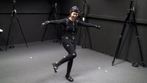
(source: https://www.sp.edu.sg/mad/about-sd/facilities/motion-capture-studio)

Now, if you don’t need extreme precision on the positions, an inexpensive piece of hardware like Kinect and a completely free software like blender (and the python libraries) can do the job!

Having fun

The whose system in action can be viewed in the video bellow. The capture was made in real time. The image of the camera and the position of the skeleton have a little delay that is negligible. That means that one can use, even with the IPC communication delay and all, as a game joystick.

Conclusions

As always, I hope you liked this post. Feel free to share and comment. The files are available at GitHub as always (see reference). Thank you for reading!!!

References

[1] – blender-kinect
[2] – PyKinect2
[3] – PyGame
1+